Upgrade of hotel Utility and Standby Generator Infrastructure Installation
Project Brief
To Design, Project Manage, Manufacture, Install and Commission a new Electricity supply generator infrastructure installation at the Caribbean hotel including the following:
• New 7 Bay 11,000 Volt ac Switchboard
• New 4 Set Generator Paralleling Control System Complete with Switchgear
• New 1400 kVA Diesel Generator to replace one of the existing 750 kVA machines
Being able to maintaining a power supply to the hotel to enable it to remain fully functional and open during the course of the upgrade works was an important factor in the clients decision to award The Generator Company the contract for this project, as was our ability to offer a turnkey solution providing our own installation technicians to work on this remote Caribbean island. The project was planned in 3 key stages:-
Stage 1: Replacement of 7 Bay MV Switchboard
The first stage of the project involved the installation of the replacement MV switchboard within a room adjacent to the existing HV switchroom, 11,000 Volts supplies from both Standby Generator and Utility were to be maintained to both switchboards until all load cables were migrated from the old switchboard to the new switchboard fitted with Merlin Gerin Genie EVO switchgear. It was crucial for a Standby Generator supply to be maintained at all times due to the frequent utility supply failures experienced in Antigua. To provide a Generator backup supply for the new MV switchboard a temporary control system was fitted to one of the existing generators, as were temporary load cables via a temporary step up transformer.
During the course of the next 5 evenings the outgoing MV load cables were transferred from the existing to the new MV switchboard by our own team of installation technicians. All of this work was carried out between the hours of 0100 and 0500 to minimise disruption to the
normal operation of the hotel.
Once all of the load cables had been migrated to the new MV Switchboard the original MV switchboard was dismantled and removed to make space for the replacement Generator Control and Paralleling Switchboard.
Stage 2: Replacement of 4 set Petbow AP600 Paralleling System and Paralleling Switchgear
The second stage of the project involved the design and installation of the new Generator Control and Paralleling Switchboard,
including the installation of new load cables to each generator and cable containment. One of the design challenges was
to provide a paralleling control system that was intelligent enough to monitor site load and start and stop automatically combinations of the 2 x 750 kVA Generators and the 2 x 1100 kVA Generators to support site load in the most cost efficient way in terms of fuel consumption and engine maintenance. This aspect of the project was not a feature of the original control system but was highlighted by our Design and Project Management team as a potential feature of the new system to the client during one the initial design meetings. The solution was achieved by adding additional control logic to the Mitsubishi Programmable Logic Controller (PLC) that is fitted as standard to our TGC1000 control system.
A further design challenge was to reduce the footprint of the new Generator Control System and LV Paralleling and Distribution Switchgear from that of the original installation which comprised of two separate panels. Our design team provided a solution that combined the case study switchgear and controls into one enclosure, and this not only reduced the footprint required but also reduced installation time and costs, thus offering a saving on the cost of the overall project.
The new generator control system was designed to incorporate all of the control aspects of the original Petbow AP600 control system, including a means of manual synchronisation. This was achieved by utilising our own TGC1000 paralleling control system which incorporates manual paralleling as a standard feature.
Enhancements to the original system which are also incorporated as standard include a single line mimic label to enable operators to see at a glance the status of the generator installation and also the ability for generator faults to be logged with a time and date stamp.
The new local control system consisted of a bespoke sheet steel welded construction enclosure rated at IP52 designed with further enhancements to withstand the harsh saline, and an often humid environment in which it is required to operate, as well as a 50°C ambient temperature, these enhancements included anti-condensation heaters and a special paint finish. The physical dimensions of the enclosure were
designed specifically for the location in which it was to be installed with top cable entry and front and rear access to all components for ease of maintenance. The panel was required to conform to FORM 4 Type 6 and operate at 480 Volts AC, 60 Hz, 3 phase and Neutral and be capable of withstanding a fault level of 50kA for 1 second.
Following the installation of the Control/Paralleling Switchboard, new local control panels were fitted to each generator to enable the existing engine wiring to interface with the new control system. New 240m² H07 RNF LV load cables were also then installed between each generator and its respective paralleling circuit breaker on the new switchboard. These cables were installed on new Ladder Rack installed by our
own installation technicians. All of the installation materials for the project were supplied by The Generator Company and were packed and shipped from our own warehouse in the UK.
The site work aspect of the project was completed within a period of 7 weeks, which was in accordance with our work schedule that was issued to the client prior to commencement of work on site.
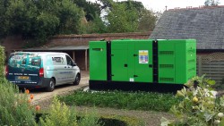
Stage 3: Supply and Installation of new 1400 kVA Diesel Generator
During stage 2 of the project it became evident one of the original 750 kVA Diesel generators fitted with a Cummins 1710 diesel engine was at the end of its serviceable life with over 50,000 hours of operation and at over 30 years old.
Discussions with the client evolved into a variation order being placed for the supply and installation of a new 1400 kVA, 480 Volt AC, 60 Hz generator powered by a Cummins KTA50G3 diesel engine. The sizing of the generator was The Generator Company’s recommendation after taking into consideration variation of site loads throughout the day and how best to achieve maximum efficiency in terms of fuel consumption and site maintenance.
Our technicians returned to site 6 months after completion of the initial project to install the replacement generator and re-commission the control system with modified PLC software that was modified to consider the three different ratings of generators now available.