Replacement Petbow AP800 Generator Control System
The Brief
To supply, deliver, install and commission a fourth generator identical to the existing sets.
To design, manufacture, deliver, install and commission a replacement five set generator-to-generator control panel incorporating the generator change-over controls.
The Project
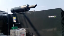
The standby power generation system comprised of 3 off Petbow AHBX400 400kW generators. Each generator is powered by a Cummins KTA19 G4 industrial diesel engine, which is flexibly coupled to a Leroy Somer LSA47.1 L10 C6/4 alternator.
Each generator is controlled locally by a set mounted control panel and remotely by the Petbow AP800 generator-to-generator paralleling control system. Each generator parallels on to a dead bus and feeds out to the switchgear panel. The project comprised of two sections. The first section was the installation and
commissioning of a fourth generator. The generator had to be identical to the original 3 sets because of the synchronising characteristics.
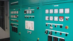
Each of the 3 original generator set mounted control panels then had to be severely modified to operate with the new control system.
The second section was to design, manufacture, deliver, install and commission a replacement generator synchronising panel. The new generator remote synchronising panel was designed to mount in to the same position as the original panel. This was a requirement because of the lack of manoeuvrability within the LV switch room and the load cables already being in a set position.
The panel was designed to incorporate a firth generator for future expansion, a mimic diagram that was to include the mains incomer status for both H.V. Transformers and the change-over controls for all of the existing switchgear.
The common control section had to be designed to offer load level demand to shut down or re-instate generators on high or low load conditions. All of the functions within the generator control system for synchronising, breaker opening / closing and automatic starting had to be fully automated with the option of being able to carry out all of the functions manually.