Standby Generator & Master Control Panel Installation
The customer required The Generator Company to design, manufacture, deliver, install and commission a new Standby generator set plus associated plant. Our scope of works under this contract included:
- 1 x 1500 kVA PRIME rated ‘open’ Cummins generator set
- Acoustic container designed to achieve 75 dBA @ 1m and incorporating an 8 hour daily service fuel tank, a lub oil top up system, lighting and small power, fire detection panel and an external cable connection box, container equipped with motorised inlet and gravity discharge louvres
- 1 x 10,0000 litre bulk fuel tank located at ground level, built on site due to access limitations
- Fuel transfer system incorporating fuel transfer pumps and control panel and circa 200m of transfer pipework
- Master Control Panel incorporating G59 and closed transition operation with multiple incomers
- Delivery to site, off-load, position & install generator sets, Master Control Panel, acoustic package, exhaust & fuel transfer system etc
- Commissioning of generator set, Master Panel and fuel transfer system
- Off-site witness test against REACTIVE loadbank
- 12 month maintenance contract
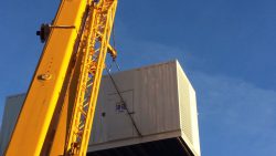
Access
The acoustic container was installed at roof level, the main body of the container was lifted to into position then the attenuation and exhaust silencers were fitted in-situ.
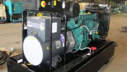
Generator Set
In line with the requirements of the site The Generator Company supplied 1 x 1500 kVA Prime rated Cummins powered generator set with a set mounted control panel and local protection circuit breaker.
Reflecting the potential for extended running periods the set was supplied with an automatic lubricating oil make-up system; this was locate adjacent to the generator set within the acoustic container and allowed the sump to be automatically topped up between services intervals as required.
Controls Specification
The generator set was supplied with a set mounted control panel suitable for facilitating single set operation with parallel function and synchronising onto a common bus, this worked in conjunction with the supplied Master Control Panel, the LV switchboard (supplied by others) and building management system (by others).
A free standing Master Control Panel was supplied as part of our scope of works, this was of our own design and tailored specifically to achieve the customer’s site requirements. Designed to work in conjunction with the set mounted parallel panel it provides functionality for automatic load add / shed and monitoring and control of the multiple breakers and bus coupler installed, the site was designed with 2 x incoming supply’s and the G59 relays for both incomers were incorporated within this panel. The Master Panel is a PLC based controller that provides supervisory and power transfer functions (when required) for multiple generator sets and incomers. In this instance it is configured to function with the Cummins PowerCommand™ digital paralleling control (PCCP) panel which is set mounted.
The PLC & HMI package controls the switchboards based on external parameters, monitors the generator set and switchboard metering via Modbus and volt free digital inputs to allow operation of the generator system automatically and unmanned. All information can be monitored via the 17” HMI screen installed, the system is menu driven and simple to follow with different levels of access available as appropriate to operator capability of engineer modifications. An additional benefit of the system is that all information available from the set mounted panel is mimicked to the Master Panel which in this instance was located in the LV Switch room; this allowed all relevant information on generator and switchboard status to be available in the same place.
A level of manual control is incorporated to enable the system to be operated manually if required.
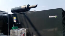
Acoustic Container
A ‘walkround’ style acoustic container was supplied, this was designed to accommodate the generator set and achieve a noise level of 75 dBA @ 1m in assumed free field conditions. The container was supplied with motorised inlet and gravity discharge louvres to seal the container when not running, an 8 hour daily service fuel tank, internal electrical package including lighting, small power and a heater, a single zone fire panel with heat detector, sounder and beacon and BMS output for interconnection with the on site building systems was also installed. Cable entry into the container was via an externally mounted Load Terminal Box designed to accommodate the incoming armoured site cables and associated control cabling.
The exhaust system was mounted on the roof of the acoustic container and comprised primary and secondary silencers to achieve the required noise level; a catalytic convertor was incorporated in the primary section of the system.
Fuel System
The generator set was supplied with an 8 hour day tank installed within the acoustic container with fuel lines extended to the outer wall of the container for feed and dump functions.
A bulk fuel tank was located at basement level within a dedicated tank room, the tank was a 10,000 litre double skin tank sized to allow the set to run for 24 hours with spare capacity for the contents of the roof mounted tank, due to the restrictions on site in respect of access to the tank room the tank had to be fabricated in-situ on site.
To transfer the fuel from the basement to the generator set at roof level a duplex fuel transfer pump set was installed on the bulk tank, the associated transfer panel was installed within the acoustic container at roof level so all controls for the generator and transfer system were in a single place, this making commissioning and ongoing maintenance etc more straight forward. The bulk tank had a remotely located fill point cabinet; this was installed complete with appropriate transfer pipework.
Fuel transfer was via circa 100m of pipe in pipe fuel feed line, this ran vertically from the tank room in a riser to the roof slab, it then ran at ceiling level (double height room) across the building before turning vertically up to roof level and across the roof to be connected to the day tank via motorised valves, further provision made for a fuel dump line to evacuate the contents of the day tank from roof level in the event of an emergency; this was also approximately a 100m long run.